First Operational |

|
General Note: This paper contains portions of an article that was published in issue #109, February 2007, of the "Z-100 LifeLine". It has been re-edited, shortened and updated with more recent information.
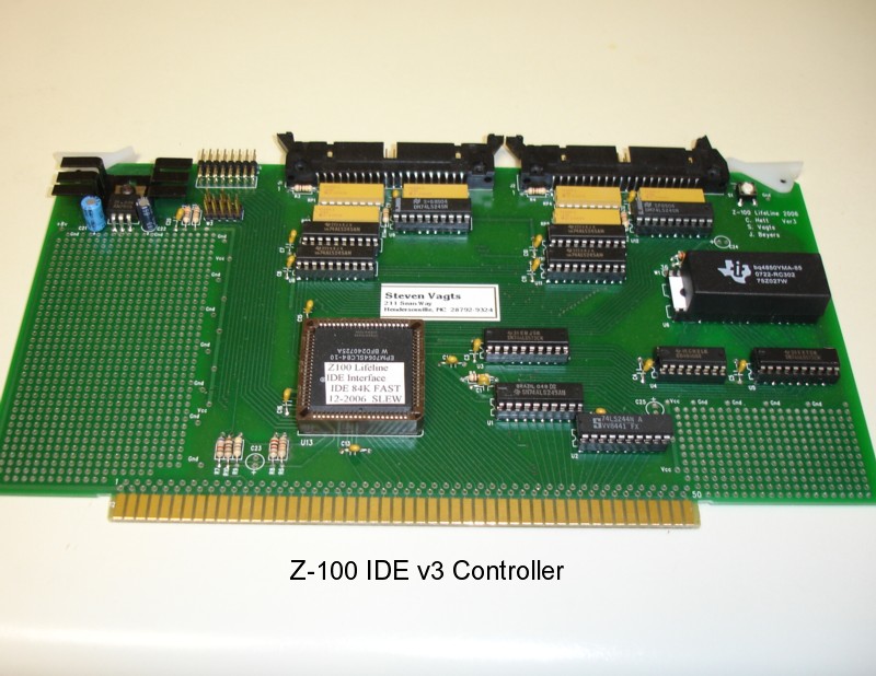
Finally, after years of work by the talented "Z-100 LifeLine" staff - Charles Hett and John Beyers - the light is visible at the end of the tunnel. While all the testing isn't yet complete, the latest version of the Z-100 IDE controller, version 3, truely looks very promising. In case you may have wondered why we were taking so long on development, and since this is really the first opportunity that I've had for showing you some pictures, I thought you might enjoy seeing the four IDE controller boards that we went through:
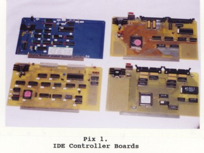 The first board (top left) was our wirewrap board. Mine (pictured) has only the NVsRAM circuit and was described back in issues #94 and #97. Charles Hett had the full circuit on his board. The second (bottom left) was our first prototype using a small Altera programmable integrated circuit, the medium-sized square in the lower left corner. The third (top right) was our second prototype version using a larger Altera programmable chip (below and left of center) that replaced many of the smaller integrated circuits. The fourth and hopefully last (bottom right) was our third prototype version. This one separated the left and right IDE connectors entirely and added several resistor packs. This one appears to have finally fixed our interference problems. I thought the next logical step would be to see how someone would install the device in an actual Z-100. So, using a version 2 controller with one of the drives that worked well with it, I decided on doing just that. The first decision was which Z-100 model would be the hardest to convert? The Z-120 "all-in-one" model had a very adaptable drive tower that I've easily converted to hold several combinations of half-height floppy and hard drives and the plastic faceplates were plentiful and easy to work with. I've found the "low profile" Z-110 models were a bit less adaptable and harder to work with. But if you already had a unit with two half-height floppy drives, or with one half-height floppy and a full-height hard drive where the hard drive's faceplate was integral with the entire plastic faceplate, conversion is easy. After much thought, I decided on an older Z-110 low profile model that sported two old full-height floppy drives with an aluminum faceplate that wouldn't serve any useful purpose anywhere else, and I just happened to have such a candidate on hand. So, follow along with me as we convert this old workhorse into a new, ready for anything, thoroughbred.
First, I dismantled the entire unit, carefully storing away the old full-height drives - you never know when someone might call looking for one of these old dinosaurs. Then I began with the power supply. Such an old model usually doesn't have the hard drive power cables and these wouldn't be necessary after the conversion either. However, for some reason this old one had the connector for the MFM hard drive data separator card, but none for the Z-217 controller card. I had never seen that before. I wonder what it was meant to power? Anyway, as I wanted the flexibility of being able to connect to old MFM hard drives if needed, I replaced the power supply with a newer model. Next, I cleaned and visually inspected the motherboard and added a new monitor ROM, v4.3. I also cleaned and inspected the other boards. As I was hoping to install a single 5-1/4" floppy and a single 3-1/2" floppy, I went ahead and completed the Barfield modifications to the floppy controller board as described in issue #29, and later again in issue #76, of the "Z-100 LifeLine". Finally, I felt ready to take the unit on a test spin. As with most complicated systems, when powering up an unknown Z-100 for the first time, I find it is always best to reduce the computer to the bare minimum number of boards to eliminate as many variables as possible for troubleshooting purposes. The reduced load also relieves pressure on the power supply, which may not have been on in quite a while, allowing the capacitors to reform properly before being placed in full service. So, I installed the power supply, motherboard, and video card, and then attached the keyboard, power cable, and monitor. Rechecking everything in place, I crossed my fingers and powered up. As expected, I got the initial "Primary Z207 Controller ERROR" because I didn't bother installing any of the controller cards yet and the floppy controller was the default device (set by section 3 of the bank of switches at S101 on the motherboard). At the hand prompt I selected the memory test and let it run. No problems. After some initial testing and troubleshooting (as this was outside the purpose and scope of this article, I've removed this section - SWV), I was ready to go.
Drive Configuration Now it is time to figure out how you want to configure your computer to accommodate one or more IDE drives. In my case, I felt one IDE drive would be sufficient. The one that worked with this particular prototype card was only 264Mb. But considering that the most popular MFM drive that I used was 40Mb, 264Mb would be much more than I would ever need. The newer IDE controllers will be able to handle four such drives. However, one consideration that you must think about is drive back-up. On a Z-100, how does one intend to back up 264Mb of data? The obvious solutions of today's PC's - the CD or DVD - won't be available on a Z-100, at least not in the foreseeable future. Tape - if you can still find such a unit? I didn't like that idea even when I just wanted to backup 20Mb of data. No, I would think that backing up one IDE drive with a second unit would be the answer. So, you may want to figure on a minimum of two drives if you are concerned about critical data. One could still be MFM, but why hang on to that dinosaur. At the low cost of used IDE drives, just use two of them. Another option is to purchase an IDE to Compact Flash Adaptor (available on the Web for about $20.00) and add a compact flash memory card, available in all sizes from about 32 Mb to 2 Gb. Be sure ot to buy the adaptors that plug directl into the IDE connector. These physically won't work with the new version 3 IDE controller because the connectors are mounted vertically at the top of the card. However, attached to a cable, the compact flash adaptor could be placed just about anywhere. Another advantage these compact flash units have is for security. Anyone having their finances on a computer should be using removable media to lock the data away when not in use. The compact flash has the advantage of hard drive media that can be treated as a floppy disk! On my unit, a proof of concept prototype, I didn't need a second drive (and this particular card didn't like two drives anyway). However, as we go through the installation, you'll see that there is plenty of room for adding a second drive right over the first. With the floppy controller (upgraded) to control a single 5-1/4" and a single 3-1/2" drive and these mounted directly over one another, I have a large bay remaining to contain two and possibly even three IDE drives, if I so desired.
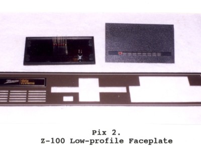 Pix 2 shows the partially modified drive bay cover of the Z-100. Originally looking like the center drive area, the right bay has already been modified to accommodate the over/under configuration of the 5-1/4" and 3-1/2" drives. This aluminum faceplate was a real monster to cut out - hours of hacksawing and filing. The newer plastic faceplates are much easier to modify. The upper left black rectangle shows the back of the modified hard drive faceplate that will cover the left (unmodified) drive bay. The upper right shows the front of an unmodified hard drive faceplate. Note: To cover the old drive slot completely, the 5-1/4" drive must be positioned precisely 5/8" above the bottom of the bay. I used wood spacers 5/8" x 3/4" x 5" cut from common 3/4" stock on a table saw. The drive combination then completely eliminated the odd looking original bay cover. The middle bay will be completely covered with the faceplate of a full-height hard drive no longer being used. These full-height faceplates should be easy enough to locate nearly anywhere that handles old drive equipment. If you have difficulty, I have plenty. It's hard to see in this picture, but the left drive cover has already been modified and shows where the breakout switch and drive LEDs for the NVsRAM and up to four IDE drives are located. Pix 6 has a better, front view.
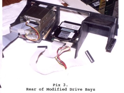 Pix 3 shows the rear of the drive bays.
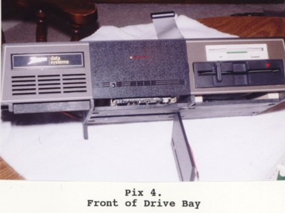 Pix 4 shows the front with the drive faceplate in place. The 5-1/4" drive is mounted on 5/8" wooden spacers to fit in the cutout of Pix 2. The 3-1/2" drive is mounted over the 5-1/4" drive using the lower drive's flat upper shield. The ribbon cable runs from the Z-207 Floppy Controller (not pictured) to the 5-1/4" drive and then the 3-1/2" drive. Note: The 5-1/4" drive (configured as drive A:) does not need a terminator resistor in this arrangement. Most 3-1/2" drives are purchased configured as drive B: and cannot be configured any other way. They depend upon a twist in the PC's ribbon cable to become drive A:. Termination in a 3-1/2" drive is also integral to it's circuitry and cannot be removed. As every Z-100 configuration will probably be different and the LED drive lights are not necessary for operation, no attempt is being made to devise a cable to mount IDE drive lights anywhere on the Z-100's exterior. For troubleshooting purposes, each board will be shipped with a bank of drive LED's mounted on the connector attached to the top of the IDE Controller Card (see Pix 1) and a breakout switch is already mounted on the board to the right of the IDE connectors. However, for this computer, I devised one possible cabling solution you might consider.
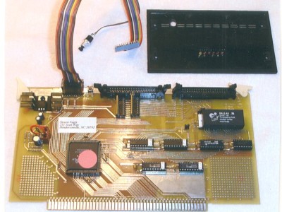
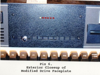
Pix 5 shows the IDE Controller Board with the drive LED ribbon cable connected at the LED connector at the top of the card. The other end of the ribbon cable ends in a SIP connector that slips onto the leads of the LED's installed in a row on the drive faceplate. Note: Use tape to hold the LEDs in place until testing is complete. You must make sure that all the LED leads are in the proper order BEFORE glueing. I tried plastic modelling glue to attach the LEDs, but the glue doesn't work very well. I recommend using a glue gun for better hold. Note: Referring to Pix 6, the drive LED's are configured so that a yellow LED indicates data is being read from the NVsRAM. The rest of the LED's are red and indicate data being written to the NVsRAM, and read/write operations to IDE drives connected as J1 master, J1 slave, J2 master and J2 slave, in that order. The last two wires from the ribbon cable are connected to a separate, normally open, pushbutton, breakout switch also installed on the faceplate. The switches are available from Radio Shack, part #275-1547.
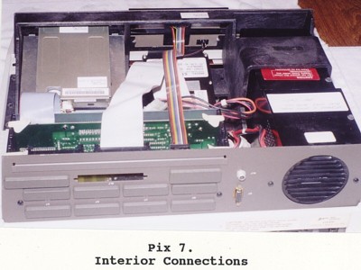 Pix 7 shows the interior of the finished configuration. So, with the hardware modifications completed, let's turn our attention to the software issues.
Programming the NVsRAM on the IDE Controller Board. The heart of the boot up operation on the IDE Controller Board is the NVsRAM chip, also commonly referred to as the EEPROM to remain consistent with the terminology used previously to describe the EEPROM on the Z-100 LifeLine SCSI Controller Card. NVsRAM is the acronym for NonVolatile Static Random Access Memory. This is memory that can be programmed and then an internal battery in the chip will hold this programming in memory until the chip is reprogrammed or erased. Programming the chip isn't difficult, but for frequent changes, it can be a pain, so I developed a couple of batch files to make programming somewhat easier. These, or something similar, will be distributed with the Controller Boards. First off, memory in the NVsRAM is limited. Depending upon the model, it can be less than 64K, 128K, 256K, 512K, or more than 1Meg. With the growing needs of Z-DOS boot files for space, it was becoming increasingly difficult to fit all the desired files on a standard 360K, 5-1/4" floppy and the 1 meg NVsRAM with a clock was going to require additional circuitry on our board. So, due to space and circuit requirements, we settled on a 512K NVsRAM with an internal clock to best suit our needs. Also, as it was desirable to minimize the space required by the boot files, I thought it best to use a handy compressing utility called PKLITE to compress the files that could be. As it turns out, everything fits comfortably on the 512K NVsRAM, with plenty of room for additional files, but in case you find yourself pressed for space for your own requirements, let's pretend that we need to do it anyway. Compacting or compressing IO.SYS and MSDOS.SYS will realize the following savings:
IO.SYS shrinks from 32915 bytes to 26344 bytes. Once compressed, the files will still execute, but cannot be changed. A full review of PKLITE can be found in issue #93 of the "Z-100 LifeLine". PKLITE can also be used on most of the other files that you may want to place on the NVsRAM if you need even more space. Note: Compressing IO.SYS does create one problem that may not make it worth all the effort. When creating bootable floppy disks using the FORMAT A:/s/v command, the compressed system files will be transferred to the newly created floppy disk. If you then run DRIVECFG on the new floppy disk, you will get the error: Version mismatch with file!!!! This is because during compression all the DRIVECFG data will have been moved from where it should be located.
The first batch file, PACK_IO.BAT, is used to compress IO.SYS.
@ECHO off Description: ECHO thru PAUSE is just a helpful reminder about what the batch file does. As PKLITE cannot operate on a system (.SYS) file, the name is changed first. PKLITE is then used to compress IO.COM and PKF00 is used to adjust the start of the new program at offset 100h instead of offset 00h. Finally, if IO-PK.SYS exists, it is deleted and the compressed IO.COM is renamed to IO-PK.SYS.
Similarly, a second batch file, PACK_DOS.BAT, is used to compress MSDOS.SYS.
@ECHO off Description: Again, ECHO thru PAUSE is just a helpful reminder about what the batch file does. As before, the name is changed first. PKLITE is then used to compress DOS.COM and PKF00 is used to adjust the start of the new program to offset 100h. Finally, DOS-PK.SYS is deleted and the compressed DOS.COM is renamed to DOS-PK.SYS. The last batch file, EPROMPGM.BAT, is used to actually program the NVsRAM on the IDE controller card. EPROMPGM.BAT copies all the files that you wish to transfer to the NVsRAM and, for my purposes, contains:
ECHO off Description: As before, ECHO thru PAUSE is just a helpful reminder about what the batch file does. The COPY commands copy the system files to the NVsRAM, followed by all the files from an \EPROMPGM directory on the IDE drive. Note: The usable size of the NVsRAM is presently limited to 507K. So ensure the files in the \EPROMPGM directory do not exceed this amount, less the size of the system files. CHKSUMEP is automatically run to calculate the checksum and place that on the NVsRAM. EPRDFILE is run to save a data file EPTEST.DAT on the default drive as a data backup (more on this later). Once completed, additional files can be copied to the NVsRAM manually, but remember to run CHKSUMEP again, and last, to validate the programming. I also recommend running EPRDFILE again to save the programming in a backup data file. Upon rebooting, the NVsRAM is ready for use. With the batch files in place, we are nearly ready.
We are used to booting to a hard drive or a floppy drive that has the DOS commands in a directory on the same drive. Now, with the NVsRAM on the IDE Controller controlling the boot process, we either place all the DOS commands in the NVsRAM or have some means to have any request for a DOS command refer to the right drive. In the past, this had always been controlled by use of the PATH command in the AUTOEXEC.BAT file. For example, the AUTOEXEC.BAT file in my computers generally looked like:
ECHO Off With this simple AUTOEXEC.BAT file executed during boot up, any DOS command on the command line would be directed to look in the root directory of the MFM hard drive unit 0, in the partition labelled Z-DOS4, with the drive letter E: assigned to it and if not found there, it would look next in the \DOS directory. As you may recall, DRIVECFG assigns drive letters to the various floppy and hard drives on the computer using Z-DOS v4. On my computers, for standardization among the many different computer configurations that I have around the house, I generally assign the first four drive letters, A: thru D: to the floppy drives; E: thru H: to the MFM hard drive partitions; I reserve drive letter I: to be mapped as an imaginary drive by assigning it to map drive A:; and finally, DRIVECFG automatically assigns the next available drive letter to the EEPROM on either the LLSCSI board or the IDE board, depending on if either is detected. The next available drive letter is then assigned to any drive and their partitions found on either board. This has worked out well for me in the past. The IDE drive, however, on my computer is assigned the drive letter K: by DRIVECFG.COM. And the NVsRAM (referred to as EEPROM) on the IDE card, is assigned drive letter J: Using the AUTOEXEC.BAT configuration above, however, now generates an error if the MFM hard drive is not attached. Physical Sector Zero is not readable, unit does not exist. So, we need to configure the AUTOEXEC.BAT file on the NVsRAM to refer to the proper drive for executing DOS commands. If there will not be any MFM hard drive system on the computer, change the AUTOEXEC.BAT file to:
ECHO Off If you intend to leave an MFM hard drive in the system, but will be booting to the NVsRAM as the primary drive, you may wish to use something as complicated as:
ECHO Off Obviously, the object is to let the computer know where to find the files you wish to run. Note: While this may still change, the IDE driver will automatically recognize two partitions on each of up to four IDE drives and assign them drive letters. Any additional partitions on drives will require the use of an IASNPART utility that will operate in a manner similar to ASGNPART. Note: All the above drive configurations have assumed that four partitions have been set aside for MFM hard drive use. If you do not intend to ever worry about an MFM hard drive again, just delete those drive letters using DRIVECFG. The IDE driver will adjust the IDE drive letters accordingly.
We have one last complication to address, and I saved it for last. Back up in the programming batch file, you may have noticed that the drive letters were changed from the ones that we had assigned automatically. This may change because presently it is somewhat confusing, but the IDE driver is configured to add a different drive letter to the NVsRAM when it is being programmed, and this causes the IDE drives to bump down to the next available drive letter after this new drive is listed. For example, the normal IO.SYS boot screen will list the drives as configured by DRIVECFG and others found as:
A: LOW Den. 48tpi 5 1/4" 34 Z207p 0 As one of several protection methods against accidently programming, or inadvertently changing, the NVsRAM programming, we felt it best to only enable programming the NVsRAM by loading a separate driver, EPROMDSK.SYS during the boot process. Therefore, CONFIG.SYS, which we'll describe in great detail in a moment, has a separate section that is enabled to load this driver only when we specifically ask for it. So, when we want to program the NVsRAM, the NVsRAM is actually enabled for programming and the IO.SYS boot screen becomes:
A: LOW Den. 48tpi 5 1/4" 34 Z207p 0 CONFIG.SYS is controlling all of this and for those of you who are still using the old three or four line CONFIG.SYS, you'll have to get used to the new expanded version. The new CONFIG.SYS was explained way back in issue #59 and it is interesting reading for those who need to boot their computer under changing configurations depending upon the applications to be used. While the CONFIG.SYS listed in issue #59 may appear very complex, it really isn't so bad once you are familiar with the outline structure. The following is a much abbreviated version with all the comment lines still included to help you along. The version you use for your computer can be edited down much further. I recommend not eliminating all the comments, however, to ease in making changes at a later date. CONFIG.SYS contains:
Rem SECTION 1 - Common Commands Section Descriptions: Section 1 lists the commands that are common to all options. Many of these commands could have been moved to the individual options to accommodate special requirements of applications. For example: a particular application may require more buffers than usual; so you would list Buffers under each option in Section 2 and specify the number for each application. Section 2 is where special drivers are loaded for their particular application. If a particular driver is needed under several options, it could be placed in Section 3 as a common block, defined as a pound sign(#) and a number. For example; the LLIDEHD driver will be required in most options. Rather than listing it individually under each, #0 is a marker placed to define those commands in Common Block #0. Section 3 lists and defines all the Common Blocks. These blocks, defined with a pound (#) sign, may be used in multiple individual options given in Section 2. Section 4 is provided for any command that has to be executed after all the drivers are loaded. Finally, finish editing the file with a CTRL-Z as an End-of-File marker, if needed. Note the INSTALL=SHARE.EXE line in the CONFIG.SYS file. SHARE is necessary and should be installed any time you are operating a system with a drive containing one or more partitions greater than 32Mb. The deal is that old "File Control Blocks" or "FCB's" cannot hold pointer information in its "Reserved Fields", on files located on disk locations past 32Mb's. FCB's will only work correctly as long as a file is physically located within the first 32Mb's of a partition's start. If part of the file lies past this 32Mb range, the FCB doesn't complain or generate an error, it just rolls the pointer value over, through zero, and gives DOS a new garbage value as an internal disk pointer. The next disk read gives junk to your program, and the next write corrupts your disk! Without going into detail, the reason SHARE is the solution is because it was already doing the required fix for a different reason in small partitions. For a more detailed explanation, see the SHARE help screen in the Z-DOS v4 help directory. Now we have all the parts in place. The only other change to worry about is the Boot command.
ROM v4.3 Boot Up Sequence Unless you have been using Autoboot all your life, you are already familiar with most of the Boot options. Remember, Autoboot can be disabled by setting section 3 of S101 on the motherboard to "On" or 0 (toward the rear of the computer). You can also get to the hand prompt by pressing the {DELETE} key at which time the computer will respond with "Boot Abort" and the hand prompt. Note: If all initial tests are satisfactory, the version 4.3 Monitor ROM will now display the Help screen before the hand prompt. Otherwise, it will display an error message and the hand prompt as in earlier ROMs. Unless you have played with the LifeLine SCSI board, you are probably not familiar with all the changes to the Boot options since version 3.0 of the ROM. So, let me briefly cover these Boot options. The Boot command will boot the Disk Operating System from a diskette, MFM hard drive, a SCSI drive from a Z-317 controller card, or a Z-100 LifeLine SCSI or IDE Controller Card. The Boot Syntax is: Boot [F1-4][Unit#][S][:partname]{RETURN}
Where:
Unit# specifies the drive unit number as set on the drive's DS (drive
S specifies a secondary floppy or hard drive controller; :partname specifies the partition name on a hard drive to boot from. To manually boot the computer, press the {B} key. With the version 4.3 Monitor ROM, the computer will now display the default boot device as set by the S101 switches on the motherboard. On my computer, the display is:
Default Booting Primary Z207 34pin Unit 0 and the computer will wait for you to type on the keyboard to give it more information. If you press the {RETURN} key, the computer will begin to boot the operating system from the default device, drive zero, as determined by the setting of switch S101 on the motherboard. This device can be a 34-pin floppy drive unit zero, a 50-pin floppy drive unit zero, the first MFM hard drive, or the bootable EEPROM on the LLSCSI board. If you press the {F1}, {F2}, {F3}, or {F4} key followed by the {RETURN} key, the computer will boot from unit zero of a specific device without regard to the settings of S101 on the motherboard. The monitor ROM can support up to four drives of each type. Therefore, you can boot from any drive by typing its unit number, 0, 1, 2, or 3 after the {F1}, {F2}, or {F3}. If the device is not present or is faulty, after about 30 seconds a "Device Error" message will appear on the screen. You can boot the computer from any partition on the Z-317 SCSI drive or MFM hard drive if there is an operating system on it. To do this, type: {B}{F3}{:partname}{RETURN} The screen will display:
Default Booting Primary Z207 34pin Unit 0 The optional {S} key is used to boot from the Secondary device (the second Z-207 floppy disk controller card, second hard drive controller card, or from the LLIDE controller card (the LLSCSI controller card is considered the primary card). If the device is not present, or is faulty, after about 30 seconds a "Device Error" message will be displayed. To Boot from the LLIDE controller card, you must type: {B}{F4}{S}{RETURN} The computer will display:
Default Booting Primary Z207 34pin Unit 0
IO.SYS Boot Screen The Boot sequence begins by displaying the IO.SYS Boot Screen. This screen looks very similar to the screen displayed during the DRIVECFG configuration process. It lists the MS-DOS Version Number and BIOS Version Number and then all the drives configured by DRIVECFG in a display window (an example is shown earlier). In the bottom of the window, more system information is displayed: MTR ROM V4.x, xxxK RAM, xxK COLOR Video, CPU, and x.xxxx MHz CPU Speed. Below the window, messages appear indicating the status of the normal boot process. These messages are: ** Initializing Motherboard Parity ** This message only appears on a power-up (cold) boot. The parity is not checked on a warm boot (when you press the breakout switch or {CTRL}-{RESET} to return to the hand prompt). Hit any key within 3 seconds for alternate CONFIGURATION It is at this point where you have three seconds (this time can be adjusted in DRIVECFG) to decide if you want to use the default CONFIG.SYS, some option within it, or a different-named CONFIG.SYS. From the CONFIG.SYS example above, we have a couple of configuration options. Press any key to interrupt the boot process. The message will then change to: Select CONFIG.SYS option (A-Z) ->_ Then we can choose {O} (the default configuration), {P} for Programming the NVsRAM, {R} for configuring a RAM disk (if a RAM card is installed), or {Z} for loading nothing or doing anything (good for troubleshooting purposes). Of course, if you have other configuration options in your CONFIG.SYS file, here's where to exercise those options. For this run, we let it time out and the computer will use the default CONFIG.SYS, displaying the message: Using default CONFIG.SYS optn. After CONFIG.SYS is executed, the AUTOEXEC .BAT file is executed and the computer will display the NVsRAM drive letter:
J:\>ECHO OFF
Programming the NVsRAM As the NVsRAM is read only once it is programmed, we must discuss the procedures for programming the NVsRAM. When we interrupt the boot process, by pressing any key at the CONFIGURATION question, the computer will replace the message with: Select CONFIG.SYS option (A-Z) ->_ Then we can press a key to choose a configuration option. To choose to enable programming the NVsRAM, we need to press {P}.
~~~~~~~~~~~~~~~~~~~~~~~~~~~~~~~~~~~~~~~~~~~
When the NVsRAM is prepared for programming, the write protection is ~~~~~~~~~~~~~~~~~~~~~~~~~~~~~~~~~~~~~~~~~~~ The computer will load the EPROMDSK.SYS driver and update the drive list in the IO.SYS boot screen to reflect new K: and L: drives:
K: 512K EPROMDSK/CLOCK (programming) and below the window, the boot session is completed when we see the DOS prompts:
J:\>ECHO OFF To program the NVsRAM from the IDE drive L: we need to change to the \EPROM directory on the L: drive and then run our EPROMPGM.BAT file that we created earlier. The series of commands are:
J:\>L:{RETURN} To program the NVsRAM from the 3-1/2" floppy drive (preparing this backup disk is explained shortly), we don't need an EPROM directory, instead we have our EPROMPGM.BAT file in the root directory and additional files in the \EPROMPGM directory. Booting to the floppy, using the same procedures given above, the command sequence is simply: B:\>EPROMPGM{RETURN} In either case, the batch file is run and a new CHECKSUM is generated and also placed on the NVsRAM. Note: EPROMPGM.BAT does not need to be run for minor changes. As long as the NVsRAM is in the programming mode, if you just wanted to add a file, the NVsRAM is treated as any other drive letter. Copy the new file to the K: drive and, when all the changes are completed, run CHKSUMEP to generate a new Checksum.
Setting the Clock Setting the Clock couldn't be easier. Simply set the date and time using the normal DOS DATE and TIME commands, then run IDECLOCK. IDECLOCK also has some other capability. For help, run: IDECLOCK ?{RETURN} Actually, anything placed after the IDECLOCK on the command line will generate the help message:
This program will Auto Calibrate the TI bq4852Y or TI bq4850Y clock on the LifeLine IDE card To set the clock, simply run IDECLOCK without anything else on the command line. IDECLOCK will then auto Calibrate the clock and set the Date and Time from the DOS setting. If successful, the computer will respond with: IDE EPROM Clock successfully set from MS-DOS date and time. To check the status of the clock, run: IDECLOCK{SPACE}{RETURN} The computer will respond with the help message and then provide the Current Calibration Setting and Current Wait States being used. On the last line, the Day of the Week, Date, and Time are displayed, with the time incrementing. For example:
Current Calibration Setting = + 04. Current Wait States = 0. Wednesday, February 14, 2007 08:53:16 Pressing any key will exit the routine.
Alternate NVsRAM Programming Once the NVsRAM has been programmed using the above procedures, there is a set of 3 programs that are of tremendous assistance in maintaining the status of the NVsRAM chip. EPRDFILE.COM - Reads all the data stored in the NVsRAM and stores it in the same directory as EPTEST.DAT. When finished running, it reports: File Successfully Written from EPROM. and EPTEST.DAT is written to the current directory. The file is 525Kb so the EPTEST.DAT command cannot be run from the NVsRAM or 5-1/4" floppy and will require a healthy chunk of a 3-1/2" floppy! For that reason, the set of three files are placed in the \EPROM directory on the IDE drive. EPCPFILE.COM - This command compares the previously saved EPTEST.DAT file with the NVsRAM again to ensure they are the same. When complete, it will hopefully report: End of Compare EPROM and File. If there are any differences, each is reported as a separate line. For example: Found in File 00h in EPROM A0h for sector 0 at Offset 645 If the files are completely different, these reports will scroll seemingly forever on the screen. Press {CTRL}-{C} to exit. EPWRFILE.COM - This command makes recovery for a corrupt NVsRAM quick and easy. It will copy the data file, EPTEST.DAT, which was automatically generated by the EPROMPGM .BAT batch file, back into the NVsRAM in the event the NVsRAM becomes corrupted for some reason other than internal failure. The NVsRAM does NOT require to be in programming mode. Note: There is a write enable jumper located beside the NVsRAM on the IDE Controller Card. The pins are not installed and it is presently enabled by a trace between the two pin holes. If you wish to disable ALL writes to the NVsRAM, including EPWRFILE, cut the trace and install pins to enable writing when necessary.
Creating a Backup Floppy In spite of all the precautions that we have built into the IDE Controller Card and NVsRAM programming, the IDE Card and NVsRAM are critical to the booting process of the Z-100. If for some reason the NVsRAM is erased, or you have to change it out, it is best to have a bootable backup disk to be able to reprogram the NVsRAM. Therefore, once the NVsRAM has been programmed and is working to your satisfaction, make a bootable 3-1/2" disk using FORMAT B:/s/v, which will install IO.SYS, MSDOS.SYS, and COMMAND.COM on the floppy to make it bootable. Caution: Running FORMAT /s/v from an NVsRAM using compressed system files will copy these compressed system files to the floppy drive. These will generate an error if DRIVECFG is subsequently run on the floppy disk. Note: While a 360K 5-1/4" floppy disk will have enough space for the critical files and could be used, it would not be able to contain all the files to fill the 507K NVsRAM. Next, create the \EPROMPGM directory and copy all the files to it from the IDE drive's \EPROMPGM directory. Finally, copy the following files to the root directory on the floppy drive:
AUTOEXEC.BAT EPROMPGM.BAT CONFIG.SYS Modify PATH in AUTOEXEC.BAT and modify EPROMPGM.BAT to load the files from the floppy drive. Next, copy any additional files as you may desire into the Root directory on the disk. This is an emergency disk and you might need to do any number of actions while troubleshooting your situation. So, such files might include, depending upon your computer configuration:
ASGNPART.COM DETECT.COM DSKCOPY4.COM Caution: Remember to leave at least 525Kb of space for the EPTEST.DAT data file generated by EPRDFILE during the NVsRAM programming. Finally, reboot to the floppy and reprogram the NVsRAM to ensure the floppy disk works as intended. Label the disk as follows:
"Emergency IDE NVsRAM Programming Disk" and store it in a safe location.
NVsRAM Test The Monitor ROM v4.3 is able to test each boot device by using the {F8} function key. This comes in handy if you suspect a problem with the NVsRAM on the LLIDE controller card. It will perform a checksum and will check it against the one stored in the NVsRAM when it was last programmed. If it is different, it will report an EEPROM Error. If correct, the test will repeat until you press the {DELETE} key. To initiate this test, type: {F8}{F4}{S}{RETURN} Upon pressing the {F8} key, the computer screen will blank and then display the following:
Default Booting Primary Z207 34pin Unit 0
TEST COUNT =
TYPE As you press the {F4}{S} keys, they are inserted at the cursor. When you press the {RETURN} key, a third line is added to the screen: Booting Secondary EEPROM Unit 0 and the COUNT begins to increment or an error message is displayed. Note: As this test is only performing a CRC check, it will only report the "EEPROM is Corrupt" message. See the Error Messages listed below. Reboot in NVsRAM programming mode using an alternate boot device and run CHKSUMEP.COM, EPWRFILE.COM, or EPROMPGM.BAT to recover. TESTIDEP.COM can be run at any time from the DOS prompt. Like the test above, it simply calculates a Checksum and compares it with the stored value on the NVsRAM. If it was successful, it reports: IDE EEPROM IS OK If not, it reports: IDE EEPROM IS CORRUPT Run EPWRFILE.COM as discussed above to recover, or reboot in NVsRAM programming mode and run CHKSUMEP.COM or EPROMPGM.BAT.
Known Software Issues As with any new hardware or software changes, some incompatibilities have to be expected and this implementation did not disappoint. The first problem has already been reported. It seems that Peachtext 5000 does not recognize the new IDE drive partitions that are detected and assigned drive letters during the boot up. It does recognize the NVsRAM just fine. Upon investigating this problem, it was found that Peachtext 5000 is confused by partition sizes greater than 32Mb. This problem will probably affect other old application programs, as well. There is no easy patch for this as each software application will probably use different routines to determine partition size. While we will look further into this problem, the easiest workaround is to restrict some partitions on your IDE drives to 32Mb or less for use by these programs.
LLIDE Controller Error Messages Possible errors that may appear during the Boot test or during the Boot process include:
Error: EEPROM is Corrupt Reason: Checksums don't match. Error: NO IO.SYS Reason: IO.SYS missing or corrupt. Error: Could not find DOS, disk not a system disk. Reason: MSDOS.SYS missing/corrupt. Error: Bad or missing Command Interpreter Reason: COMMAND.COM missing or corrupt.
Error: ERROR: No LifeLine IDE Drives Detected!
Reason: Drive not detected! Check cables and power. Error: Drive not listed on IO Boot Screen or Info Wrong.
Reason: Drive may be incompatible w/LLIDE card. Try another drive. For any error messages involving the NVsRAM, all errors except mechanical or internal failure can generally be corrected by running CHKSUMEP.COM, EPWRFILE.COM, or EPROMPGM.BAT. See the section on programming the NVsRAM above for the procedures.
Advantages of an IDE controller Besides the obvious about adding a high capacity hard drive to the Z-100 and the declining reliability and availability of MFM hard drives, some persons have older Z-100's that never had the power cables to upgrade to a hard drive system. This upgrade requires NO additional power connectors. It DOES require upgrade to Z-DOS v4.06 and MTR-ROM v4.3, available at nominal additional cost with the IDE Controller Board. A major advantage of the IDE upgrade, is the greatly reduced power requirements. If you are replacing an MFM hard drive setup with an IDE drive setup, instead of powering a data separator card and a massive Z-217 controller card with their hefty power requirements, the new IDE controller requires a small 5 volt regulator that barely gets warm, and that's the warmest part on the board, even at 10 MHz! If the power supply fan noise had been driving you nuts in the past, there may be a possiblity of finally being able to replace the fan with a slower or slightly smaller unit, though it is still not recommended!
Closing I think I've shown that even the lowly dual-floppy Z-100 can be easily converted into a hard working, proud machine with a little labor of love. I hope this exercise has helped you to make an informed decision as to whether you want to upgrade your Z-100 to this exciting new capability. Remember, however, the order for production IDE controller boards will probably be a one-time deal as board costs increase dramatically with small orders. As I hope to place our order in the first week in May, please get your $100.00 deposits to me as soon as you can. For additional information on expected costs, please see issue #94. Once we have the hardware running, we will once again turn our attention to the software changes needed to take full advantage of this new capability. Stay tuned for great things to happen.
|


 HOME Page
|
 LifeLine Page
|
 Z-100 Page
|
 Repair Page
|
|
Copyright © 2012, Steven W. Vagts Revised -- January 24, 2012 |
