|
Z-207 Floppy Controller Troubleshooting |

|
General Note: This article was published in the March-April 2005 issue of the "Z-100 LifeLine", issue #98. WARNING: The following fix requires some knowledge of electronics and soldering skills! Try this ONLY AT YOUR OWN RISK! WARNING: All-In-One users MUST KEEP CLEAR of the CRT power cables, the CRT second anode (the thick single cable going to the top of the CRT) and the high voltage transformer on the vertical video board during computer operation. Voltages in these locations are DANGEROUS.
In addition to the typical part failure experienced by any electronic product, the Floppy Disk Controller is subject to drift caused by aging parts on the card. If you are experiencing increasing read/write errors, but the card is still working, it might be prudent to have the card recalibrated by someone with the tools to perform that function or you may attempt to apply the following troubleshooting procedures. The following information is compiled from the Z-100 Technical Manual, the Floppy Disk Controller Card Model H-207 Assembly Manual, and personal experience. The intent of this article is to provide troubleshooting information for those wishing to repair their own Floppy Disk Controller Card. However, please understand that there is a risk to further damaging your controller and your computer. Please proceed only at your own risk.
Troubleshooting Chart PROBLEM: Drive access light does not turn on when a diskette is booted. POSSIBLE CAUSE:
1. Check for proper connections of the floppy cable inside the computer,
PROBLEM: All diskette access lights turn on and remain on. POSSIBLE CAUSE:
1. Drive cable is connected with the marked edge on the wrong side.
PROBLEM: Two drives turn on when a boot operation is selected. POSSIBLE CAUSE: 1. The two drives have their selection jumpers programmed the same.
PROBLEM: Computer will not accept a boot command, returns to hand prompt, or starts to boot, but freezes and requires reset. POSSIBLE CAUSE:
1. Be sure diskette is bootable.
PROBLEM: Upon Power Up, the message "Primary Z207 Controller Error" or "Device Controller Error" is displayed before the hand prompt. PROBABLE CAUSE:
1. The controller card of the Default Boot Device is not installed,
PROBLEM: Capacitor C35 fails on 85-2807-1 model Disk Controller cards. POSSIBLE CAUSE:
1. According to Field Service Bulletin FSB-Z100-31, if the Disk Controller
PROBLEM: The disk drive does not stop running or runs longer than about 20 seconds after the last access. POSSIBLE CAUSE:
1. Check and/or replace C30, a 47 uF, 6v capacitor in the one-shot time
PROBLEM: The computer is reporting soft read/write errors. POSSIBLE CAUSE:
1. Aging parts on the Disk Controller may have drifted off calibration.
PROBLEM: FORMAT verification fails after track 23 on 5" drives; after track 43 on 8" drives. POSSIBLE CAUSE:
1. Failure in the Precompensation Circuit.
PROBLEM: Precompensation will not adjust. POSSIBLE CAUSE:
1. According to Field Service Bulletin Z100-041, if the pulse width at
PROBLEM: Erratic Write Operation POSSIBLE CAUSE:
1. According to FSB-DK-025, early model #85-2807 boards did not include
PROBLEM: Running DIAG, the Heath/Zenith Diagnostics Program, shows a Head Load Time Error and suggests checking U33 and U15. POSSIBLE CAUSE:
1. Replace U33 and U15 as recommended.
PROBLEM: CP/M will boot from a floppy, but Z-DOS gives an I/O error. POSSIBLE CAUSE:
1. According to FSB-DK-027, check U31 (74LS365A, #443-1039) for a
Calibration Procedures Equipment Needed: You will need the following equipment to most precisely calibrate your Disk Controller Card:
* A digital voltmeter (DVM) with at least a four-digit readout. NOTE: The H-207 Assembly Manual provided a simple circuit for calibrating the Disk Controller kits. It is provided toward the end of this article.
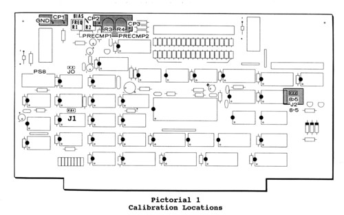
Precompensation Calibration Write precompensation corrects for "bit shift" distortion. This bit shift can be seen electronically when you read a data stream from a diskette. Data pulses which are recorded close together when read back, appear to spread apart. Precompensation advances or retards the data pulses as they are written so the pulses are properly spaced when read back off the diskette. All Heath/Zenith 5-1/4", 48 tpi, floppy disk drives require 120 ns of precompensation on tracks greater than 23. Also, all Heath/ Zenith 8" and 5-1/4" 96 tpi drives require 120 ns of precompensation on tracks greater than 43. Usually, two values of precompensation are needed: one for 5.25" drives and one for 8" drives. Accordingly, there are two precompensation adjustments on the Disk Controller Card. Potentiometer R3 (PRECMP1) is used to set the lower value of precompensation and potentiometer R4 (PRECMP2) is used to set the higher value of precompensation. Pictorial 1 shows the locations of these potentiometers. Jumper J2 selects whether the 5.25" or the 8" drive will receive the lower value of precompensation. Pictorial 1 shows the location of J2 on the Card. While referring to Pictorial 1, perform the calibration as follows:
1. Locate R3 and R4 on the Disk Controller Card.
2. Insert the Disk Controller into the S-100 bus. 3. Attach the oscilloscope's probe to CP3 and the probe's ground clip to GND.
4. Determine the values of write precompensation that the 5.25" and 8"
5. Format a blank 8" diskette in any of the 8" drives by running FORMAT.
6. Format the 5.25" diskette. While FORMAT is running, turn R4 (PRECMP2)
7. If you have both 5.25" and 8" drives, perform the next step.
8. Cut the foil on the circuit board that connects the middle hole of
9. Format a blank 5.25" diskette in any of the 5.25" drives using FORMAT.
10. Format the blank 8" diskette. While FORMAT is running, turn R4 (PRECMP2)
11. Remove the oscilloscope probe.
Data Separator Calibration While referring to Pictorial 1, perform the calibration as follows: 1. Turn the computer on and wait five minutes to reach operating temperature. 2. Make sure the disk drives are not selected.
3. Set the DVM's voltage range to 2 Vdc and attach the common lead to GND 4. Adjust R2 (BIAS) for a reading of 1.400 Vdc. 5. Remove the voltmeter test leads. 6. Set the six-digit frequency counter to count 4 MHz. 7. Attach the shield lead to GND and the signal lead to CP1. 8. Adjust R1 (FREQ) for a reading of 4.000 MHz.
9. Repeat Steps 2 through 8 until there is no further improvement and
10. Remove the test leads and turn the computer off.
NOTE: Format the blank diskettes used in this procedure again before
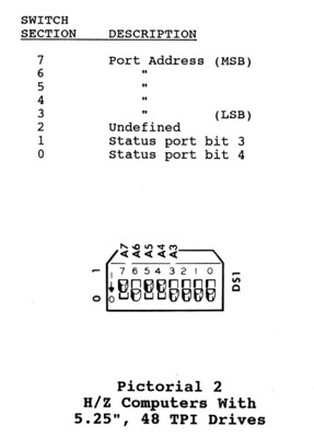
H/Z-207 Port Address The H/Z-207 Floppy Disk Controller Card occupies a block of eight contiguous I/O port addresses beginning on an 8-bit boundary. The low-order six address bits in this block of eight ports are actually used. The port address is selected by sections 3 through 7 of switch DS1 on the Card. Switch section 7 selects the most significant bit. Heath/Zenith Computers use port address B0 hex. Switch sections 0 and 1 are used to control bits 3 and 4 (with 0= least significant bit) of the status port, which can be read at I/O address BASE + 5. NOTES:
1. H/Z software uses switch section 0 for 48/96 tpi drive selection.
Other Configurable Options Please refer to your Z-100 User's Manual to configure the following two items, if needed. Disk Controller Clock Speed The H/Z-207 Floppy Disk Controller Card is configured to operate with a CPU that operates faster than 3 MHz. If the Disk Controller is to be used with a CPU that operates at 3 MHz or SLOWER, a minor modification must be made to the board at J1. Disk Controller VI Lines The Vectored Interrupt lines (VI) are properly configured to operate in a H/Z-100 computer. If you will be using the Disk Controller with a different manufacturer's computer, you may need to configure the VI lines by installing jumper wires.
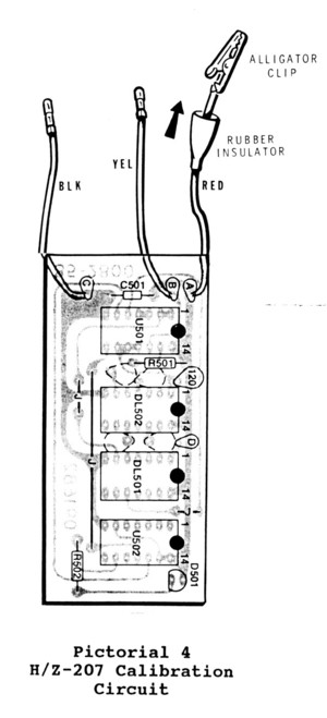
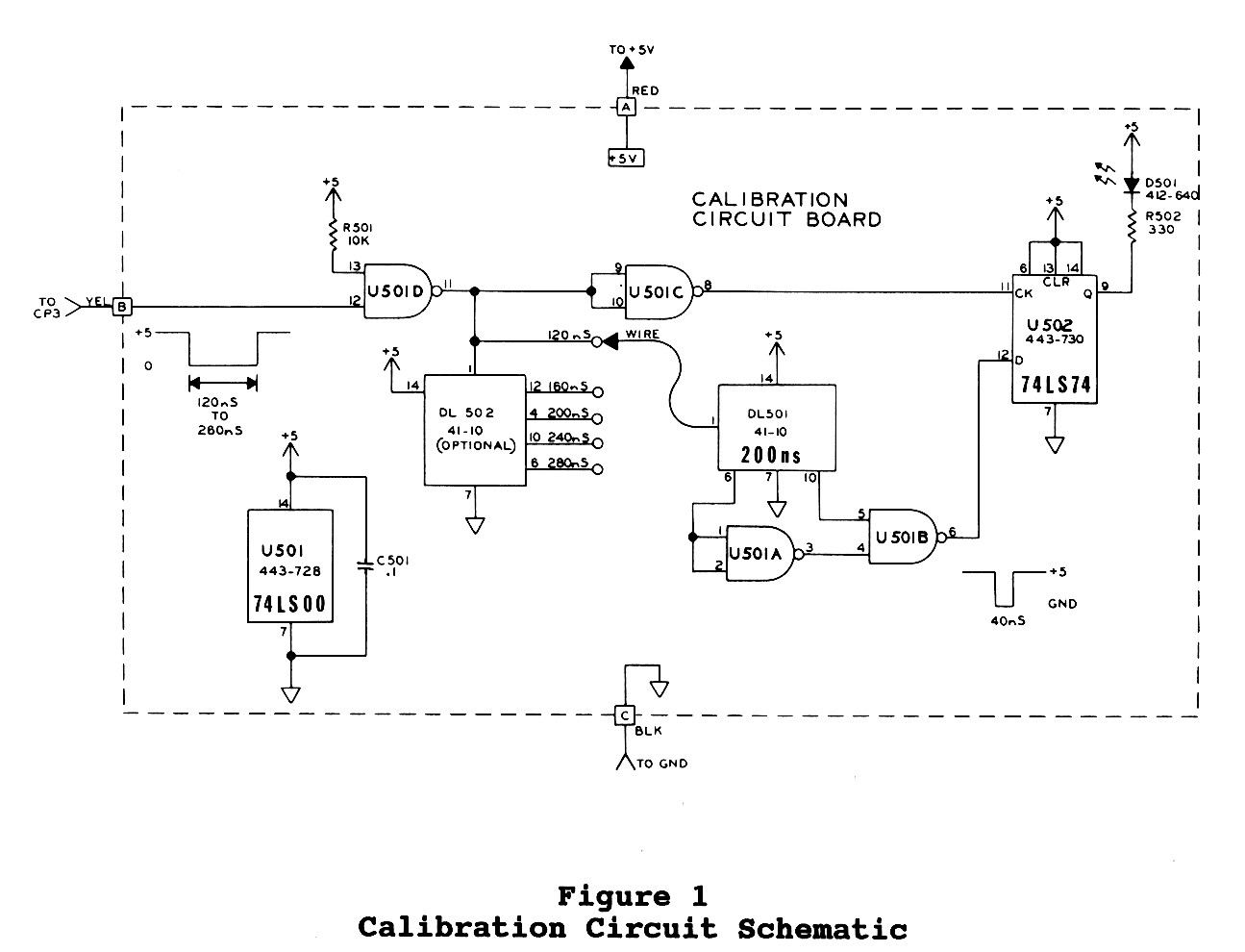
Constructing a Calibration Board Pictorial 4 shows the circuit board that was constructed during assembly of the H-207 Floppy Disk Controller Board. A similar board can be constructed on a standard plug board. The parts are easily found from spare H/Z-100 computer boards. DL501 and DL502 are the standard 200 ns Delay Line found on the Motherboard or Z-205 Memory Card. DL502 is optional and is only needed if you intend to use this circuit with drives that require more than 120 ns of write precompensation. The only critical construction note is to make the wire connecting pin 1 of DL501 to pin 9 of U501 no less than 2" long. Figure 1 shows the circuit schematic.
Heath Drive Calibration Caution: The procedures given earlier use an oscilloscope and frequency counter, reportedly making them much more accurate and preferred over the following procedures, which can damage your controller card or even the computer if improperly used. The following procedures are only provided as an alternate method to be used if the special equipment used above is not available. Well, since I wrote this many years ago, I've found that those boards that I used the oscilloscope on were having difficulty formatting drives. I've found that the resistor pots were turned just slightly too far clockwise - maybe my Heath computer scope isn't accurate enough! The circuit board and alternate calibration procedure picked up on this and I've since found that using the circuit board was actually the better procedure! If a frequency counter is available, perform the voltage and frequency adjustment as outlined in the Data Separator Calibration section above. If the frequency counter is not available, perform the alternate Data Separator calibration procedures, next.
Alternate Data Separator Calibration Calibration Preparation:
1. Locate R1 (FREQ) on the Disk Controller board and turn it 30 (thirty)
CAUTION: While the following procedures could be used without a spare
2. Locate a spare 40 pin IC socket and bend all of the pins inward under 3. Remove U22, the FD1797 controller chip, and carefully set it safely aside.
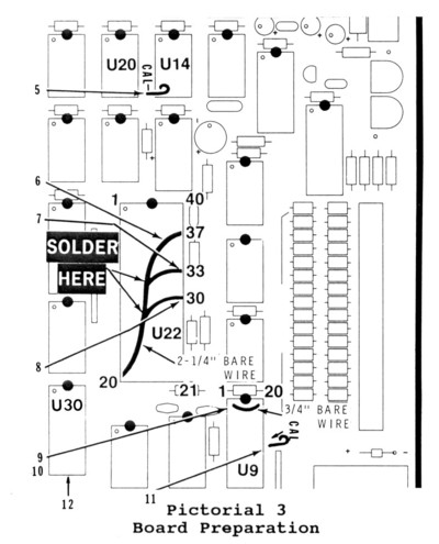
4. Install the new 40 pin socket into the empty U22 socket, ensuring that Refer to Pictorial 3 for the following steps.
5. Cut a 1/2" bare wire. Then bend a loop in one end of the wire and
6. Cut a 2-1/4" bare wire, bend 1/4" at each end, and insert the wire
7. Push a length of bare wire into socket hole 33 of U22, solder it to
8. As before, push a bare wire into socket hole 30 of U22, solder it to
9. Remove U9, 74LS241, from its socket and set it carefully aside. 10. Install a 3/4" bare wire into socket holes 1 and 20 at U9.
11. Cut and install another 1/2" hooked bare wire at the CAL hole at 12. Remove U30, 74LS273, and set it aside. The card is now prepared for the Alternate Data Separator Calibration procedures next.
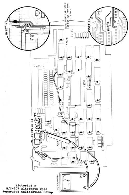
Alternate Data Separator Calibration: Refer to Pictorial 5 for the following steps.
1. Install the Z-207 Controller Card, less the three IC chips and
2. Using a high impedance DC voltmeter (10M ohm or greater), select 3. Connect the common (or negative) test lead to test point "GND". 4. Connect the positive voltmeter lead to test point "CP2".
CAUTION: When the all-in-one computer is turned on, high voltage is 5. Plug in your computer and turn it on.
6. Adjust control R2 (BIAS) for a meter reading of 1.40 Vdc. 7. Turn off the computer, unplug the cable, and remove the Controller Card.
8. Cut a 5" white wire, remove 1/4" of insulation from each end, and
9. Reinstall the circuit board into the computer and reconnect the 10. Turn on the computer. NOTE: In the next step you will adjust the R1 (FREQ) control for a meter reading of 1.40 Vdc. It is normal for this voltage to start at about 1 volt. Then as you rotate the control counterclockwise, this voltage may gradually drop to near zero, and then jump to approximately 2 volts. Rotate this control backwards (clockwise) to locate the FIRST place where you can obtain 1.40 volts. If your initial voltage reading is greater than 1.4 volts, adjust the R1 (FREQ) control counterclockwise until you find the FIRST position at which you can obtain a 1.40 Vdc reading. If you continue turning counterclockwise, you may find another point that will give a 1.40 Vdc reading. This second point is the wrong one; do not use it.
11. Adjust R1 (FREQ) counterclockwise for a meter reading of 1.40 Vdc
12. Place the top cover on the computer and allow it to operate for 13. Turn off the computer, unplug the cables and remove the Contoller Card. 14. Remove the 5" white wire from the component side of the Card.
15. Remove the top 40-pin IC socket from U22 and reinstall the FD1797 16. Reinstall U30, the 74LS273 IC. 17. Remove the top socket from U9 and reinstall U9, the 74LS241 IC. Proceed with the Alternate Write Precomp Calibration procedures next. Alternate Write Precom Calibration:
1. Turn control R3 (PRECMP1) fully counterclockwise.
2. Connect the red wire coming from the calibration circuit board to
3. Lay the calibration circuit board on the drive shelf as shown if you
4. Install the Controller Card into any of the card cage slots and connect
CAUTION: When the all-in-one computer is turned on, high voltage is 5. Turn on the computer and boot up either Z-DOS or CP/M. 6. Locate a blank soft-sectored diskette and insert it into any disk drive.
7. Run FORMAT, and as the diskette is being formatted, adjust R3 (PRECMP1)
8. Open the drive door, turn off the computer, remove the calibration This completes the calibration of your Controller Card.
NOTE: Reformat all blank diskettes used during these procedures
|

 HOME Page
|
LifeLine Page
|
Z-100 Page
|
Repair Page
|
|
Copyright © 2009, Steven W. Vagts Revised -- December 15, 2009 |